Creating Your Floor Plan
A floor plan is a scaled diagram of a room, building or outdoor venue viewed from above. Because the floor plan gives the program the boundaries within which objects (tables, chairs, etc.) can be placed, all venues must have at least one floor plan.
The floor plan may include measurements, doors, windows and other fixtures as necessary. This topic discusses importing a floor plan image, drawing and scaling the first wall of the floor plan and then completing the floor plan.
- Click or tap the Place Library sidebar option
 on the left-hand side of your screen to see your list of venues, and tap the arrow button
  at the right of a "place" or venue to open it.
Result: The Place Details window opens for the selected place.
Note: SeeAdding a New Place for information about creating a new place in the Place Library. - In the Floorplans panel at the bottom left, click the name of an existing floorplan or click the Add New button
 to add a new floorplan.
Result: You are placed in Floor Plan Mode. A purple square, measuring 30 feet for each of the four walls, displays.
Note: Every "place" automatically has a square "Default Floorplan" assigned to it measuring 30' x 30'. This floorplan can be deleted or its name can be edited in this Floorplans panel.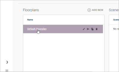
- Click/tap the Edit button
 , located on the upper left-hand corner of your screen.
Result: Various design tools become available in the toolbars on all corners of the Floor Plan Mode. - Remove the original 30' square floorlplan by clicking/tapping the Delete All button
 at the bottom left of the screen and then clicking/tapping Delete Rooms (no image is present).
Important Note: This step is only for the default floorplan automatically created by the program. Be careful not to delete rooms or images you have already customized. - Click/tap the Set Floorplan Image button
 , located in the toolbar at the bottom left of your screen.
Result: The Import Floorplan Image window opens. - Click/tap Upload File.
- Browse to the stored image of your file.
- Double-click/double-tap to select the floor plan.
Result: The image displays, zoomed-in, in the Import Floorplan Image window.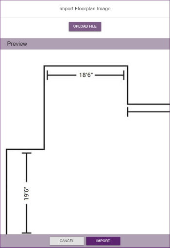
- Click/tap the Import button, located at the bottom right-hand side of the window.
Result: The selected image is imported and appears onscreen.
Note: The image will most likely be off-center and even spilling off the screen. Drag image to center it onscreen, and use the "plus" and "minus" buttons at the bottom right of the display (or use the wheel of your mouse) to zoom in or out, respectively.
- Ensure you are in Floor Plan mode. (See the topic above.)
- Identify the longest wall in the floor plan image for which you have a measurement.
- Use your mouse wheel to zoom in on the entire wall from Step 2 in order to make the tracing process easier and ensure accuracy. If using a tablet or other mobile device, tap the plus sign, located in the toolbar on the bottom right-hand side of the screen.
Note: To trace a wall, you must be able to see both of its endpoints.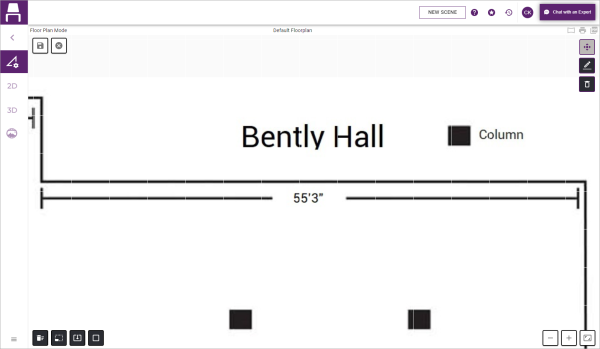
- Click/tap the Draw Image button
 , located in toolbar on the upper right-hand side of your screen.
Result: A round, purple tracing tool now follows your cursor as you drag. - Click/tap the starting point of your wall and trace along the wall to its endpoint.
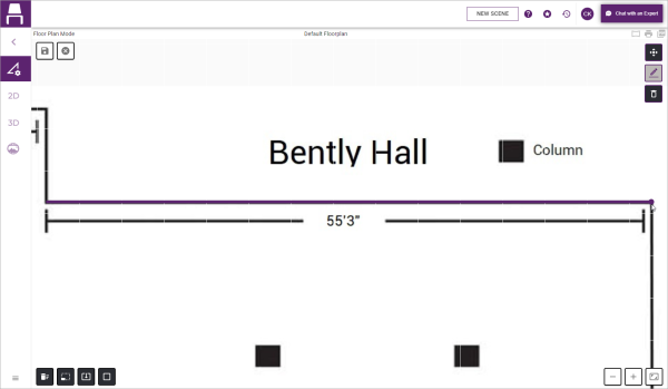
- Click/tap the endpoint of the wall.
Result: An orange line indicating the wall will appear displaying a dimension.
Note: The dimension of this new wall and the original wall in your floor plan will NOT yet match.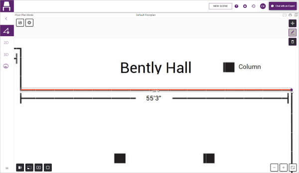
- Hit the [Esc] key on your keyboard, or on a tablet tap the Draw Image button (pencil) at the top right of the screen again to exit drawing mode.
- Make careful note of the dimensions of the new wall you just drew (orange line) and also of the original wall in your imported floor plan.
- Click the Scale Floorplan button
 , located in the toolbar on the lower left-hand side of your screen.
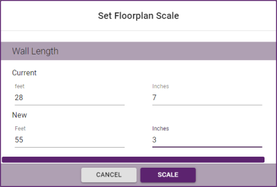
Result: The Set Floorplan Scale window opens. - Enter the dimensions of the wall you just drew (orange line) into the Current Feet and Current Inches fields. In the example above, you would enter 28 into the Current Feet field and 7 into the Current Inches field.
- Enter the dimensions of the original wall from your import file into the New Feet and New Inches fields. In the example above, you would enter 55 into the New Feet field and 3 into the New Inches field.
- Click the Scale button.
- Verify that the length of the traced wall matches the length of the wall from the original floor plan.
Note: If the traced length does not match, you can adjust the length by floating your mouse over the traced wall, then clicking/touching and holding/dragging an end point until both lengths match. OR you can follow Steps 9-11 above to re-scale the wall, entering the newly scaled dimensions for the traced wall (orange line) in Step 10.
- Complete your floor plan by moving on to the section below.
- Click/tap the Draw Image button
 again to return to drawing mode.
Result: A round, purple tracing tool now follows your cursor as you drag. - Click/tap the starting point of the next wall adjacent to the wall you traced in the section above.
- Click/tap the endpoint of that wall. Be careful to trace right through doorways and exits; do not stop at them.
Result: A new orange line appears indicated the traced wall. - Repeat Steps 2 & 3 to trace all remaining walls - being careful to include only areas where furniture and other objects will be placed. (Do not include stairways, bathrooms, storage areas or hallways intended simply for traffic flow.
Result: When you click the last endpoint in your floor plan, all walls will be instantly connected and the space will appear shaded (see image below).
- [Optional] To delete and replace a wall, click/tap the Delete Line button
 at the top right of the window and click/tap the wall you want to delete. Then click the Draw Image button (pencil) and retrace the wall.
Note: If a wall is deleted, the floor plan will not longer appear shaded and all remaining walls will go back to being orange until the deleted wall is replaced and all wall endpoints are once again connected. - Repeat this process to trace any interior walls, again excluding doorways.
- [Optional] Click the Set Wall Information button
 , check the box next to Include Walls and enter a wall height if you want walls to be visible for this space in 3D viewing.
Result: After saving the floor plan and viewing in 3D, plain walls will appear. See Selecting Paint and Flooring Options for more information.
Note: Outside venues or venues used solely with 360-Degree Photosphere might not require walls. See Creating or Importing 360-Degree Photos for more information. - Optionally add doors, windows, columns and other fixtures. (See Adding Permanent Fixtures (Doors, Windows, Columns, etc.).)
- Click/tap the Save button
 at the top left of the floor plan to save your changes.
See Also: